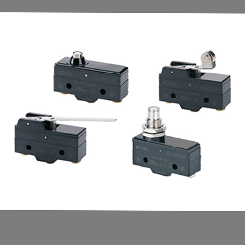
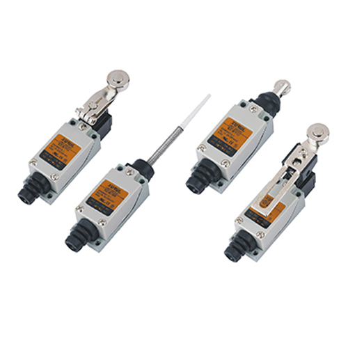
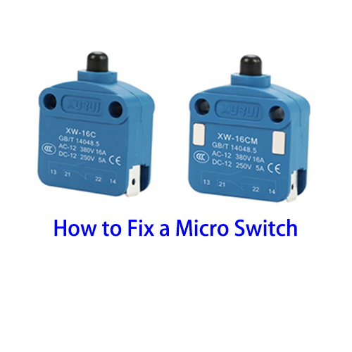
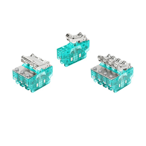
In many electrical and mechanical systems, micro switches play a vital role. Whether they work properly is directly related to the performance and safety of the system. Therefore, it is particularly important to master the method of judging whether the micro switch is damaged. The following will introduce the relevant steps and key points in detail.

I. Visual Inspection
♦ Examine the Switch Body
Check for any visible cracks, breaks, or deformities in the plastic or metal casing of the micro switch. A damaged body could potentially affect the internal components and their operation.
Inspect the terminals to see if they are loose or corroded. Loose terminals may lead to intermittent electrical connections, while corrosion can impede the flow of electricity.
♦ Inspect the Actuator
If the micro switch has a button, lever, or roller as an actuator, assess its condition. Ensure it moves freely and smoothly. A stuck or jammed actuator may prevent the switch from operating correctly.
Look for any signs of wear or damage on the actuator, such as excessive friction marks or broken parts.
II. Electrical Testing with a Multimeter
(1) Set Up the Multimeter
Turn on the multimeter and set it to the resistance or continuity testing mode. In the resistance mode, the multimeter measures the resistance between two points, and in continuity mode, it checks if there is an unbroken electrical path.
(2) Test the Normally Open (NO) Contacts
Locate the common terminal (usually labeled "C") and the normally open terminal (usually labeled "NO") of the micro switch.
Place one multimeter probe on the common terminal and the other on the normally open terminal.
When the micro switch is in its normal, unactuated state, the multimeter should show a high resistance value (ideally, an open circuit or infinite resistance). This indicates that the contacts are not touching and the circuit is open.
Now, actuate the micro switch (press the button, move the lever, etc.). The multimeter reading should change to a low resistance value, indicating that the contacts have closed and the circuit is now conducting. If the resistance value does not change as expected or remains high, it suggests a problem with the NO contacts.
(3) Test the Normally Closed (NC) Contacts
Identify the common terminal and the normally closed terminal (usually labeled "NC").
Connect the multimeter probes as before.
In the unactuated state, the multimeter should show a low resistance value (close to zero or a very small resistance), meaning the contacts are closed and the circuit is conducting.
Actuate the micro switch. The multimeter reading should now change to a high resistance value, as the contacts have opened and the circuit is broken. If the resistance does not change appropriately, there may be an issue with the NC contacts.
(4) Check for Consistency
Repeat the actuation of the micro switch 5 - 10 times and monitor the multimeter readings. The readings should be consistent. If there are significant fluctuations or if the switch fails to change its state reliably, it indicates a faulty micro switch.
III. Functional Testing in the System
● Reinstall the Micro Switch (if Removed)
If the micro switch was taken out for testing, reinstall it in its original position in the device or system. Make sure it is properly connected and secured.
● Observe the System Operation
Operate the device or system in the normal way and pay attention to how the micro switch functions. For example, if it is a switch for a door sensor, open and close the door and see if the associated function (such as turning on a light or sounding an alarm) works as expected.
If the micro switch is supposed to control a motor, check if the motor starts and stops at the correct times when the switch is actuated. If the system does not respond correctly or if there are erratic behaviors, it may be due to a bad micro switch.


