I、Preparation
1. Tools & Materials Needed
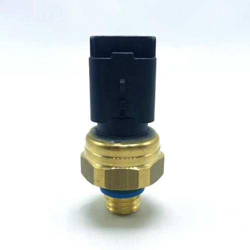
√ Limit switch (confirm type: Normally Open NO / Normally Closed NC)
√ Wires (choose gauge based on voltage/current; stranded wire recommended)
√ Tools: Wire stripper, screwdriver, multimeter, terminal block (optional)
√ Power supply (DC/AC, matching the switch’s rated voltage)
√ Control device (e.g., PLC, relay, motor controller)
2. Understand Switch Types
• Normally Open (NO): Contacts are open when untriggered, close when activated.
• Normally Closed (NC): Contacts are closed when untriggered, open when activated.
II 、Wiring Steps (Example: Motor Control Circuit)
1. Power Off & Plan the Circuit
• Disconnect all power sources to avoid electric shock or damage.
• Sketch a simple wiring diagram, labeling switch terminals (COM common, NO/NC), power poles, and control device ports.
2. Connect Switch Terminals
• 2-Terminal Switches (Single Pole): Connect COM to the power positive/signal line, and NO/NC to the control device input (e.g., PLC I/O port).
• 3-Terminal Switches (COM + NO + NC): Use COM as the common terminal. Connect NO for circuits that activate when the switch is triggered, or NC for circuits that deactivate when triggered. (Example: For a "trigger-to-connect" function, use COM + NO; for "trigger-to-disconnect", use COM + NC)
3. Integrate into the Control Circuit
• For PLC/Relay Systems: Connect the switch output to the control device’s input terminal (e.g., PLC’s X0), with the other wire to the power negative/common.
• For Motor Control: Series the switch contacts with the motor relay coil circuit (triggering the switch cuts the coil power, stopping the motor).
4. Grounding & Mounting
• Ground metal-enclosed switches (connect PE terminal to equipment ground) to prevent static interference.
• Secure the switch to the mechanical limit position using screws/clips, ensuring the actuator (lever, roller) moves freely.
5. Power On & Test
①Restore power and manually trigger the switch; use a multimeter to check contact continuity.
②Run the connected equipment and test the limit function: the device should stop/reverse/alarm when the switch is triggered.
③If issues occur (e.g., loose connections, false triggers), power off and check wiring tightness or switch alignment.
III、Safety & Best Practices
1. Electrical Safety
• Never exceed the switch’s rated voltage/current; use a flyback diode for inductive loads (e.g., motors).
• Use shielded cables for long-distance wiring to reduce EMI interference.
2. Installation Tips
• Avoid overstressing the switch actuator (e.g., bending levers); clean contacts with alcohol if oxidized.
• Choose waterproof switches for outdoor/wet environments; seal wire connections with insulating tape or waterproof connectors.
3. Troubleshooting Table
| Issue | Possible Cause | Solution |
|---|---|---|
| Device doesn’t stop when triggered | Loose wiring, oxidized contacts, wrong switch type | Tighten terminals, clean contacts, verify NO/NC selection |
| False triggering | Misaligned switch, shorted wires | Adjust mounting position, test wire insulation with a multimeter |
IV、FAQ
1. How to tell NO and NC contacts apart?
→ Use a multimeter on resistance mode: NO shows infinite resistance (open) when untriggered, NC shows near 0Ω (closed).
2. Can I connect multiple limit switches in series/parallel?
→ Yes! Series for "AND" logic (all must trigger), parallel for "OR" logic (any trigger activates). Follow your control system’s logic design.
3. Are DC and AC wiring different?
→ Yes. DC requires polarity (positive/negative), while AC is non-polarized but must match voltage ratings. Always follow the manual’s wiring diagram.
V、Conclusion
Proper limit switch wiring relies on knowing contact types, matching circuit specs, and prioritizing safety. Step-by-step testing and secure installation ensure your equipment stops precisely at limit positions, preventing mechanical damage. For complex setups, consult the device manual or a professional engineer.