In the field of industrial automation, limit switches play a critical role. How do they work? What are the mysteries of their principles and structures? This article will analyze them in depth and give you a comprehensive understanding of the working mechanism and related key points of limit switches.
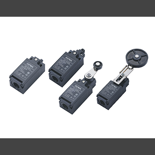
I. Basic Components
1. Mechanical Actuator Types
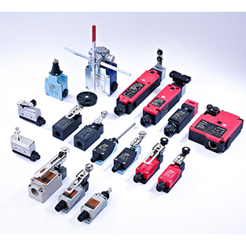
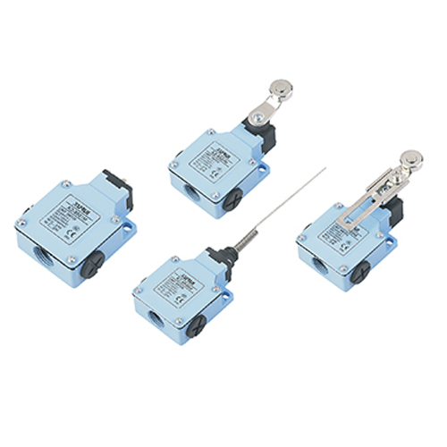
The mechanical actuator is the part of the limit switch that physically interacts with the object or moving part being monitored. It can be in various forms such as a lever, roller, or plunger.
For example, in a conveyor belt system, a roller actuator might be used. As the conveyor belt moves, the roller rolls along with it. When the belt reaches a certain position, the roller hits a stop or an obstruction, which causes the actuator to move.
2. Electrical Contacts Materials
Inside the limit switch, there are electrical contacts. These contacts are usually made of conductive materials like copper or silver alloys.
In the normal state, the contacts can be either open or closed. For example, a normally open (NO) contact is open when the actuator is in its untriggered position. When the actuator is moved due to the object reaching the limit, the NO contact closes, allowing an electrical current to flow through the circuit.
3. NO and NC Contact Functions
Conversely, a normally closed (NC) contact is closed in the normal state and opens when the actuator is triggered. The choice between NO and NC contacts depends on the specific control logic of the system.
For example, in an emergency stop circuit, a NC contact might be used. When the limit switch is activated, the NC contact opens, breaking the circuit and stopping the machine.
II. Operating Principle
1. Initial State Setup
In the initial, unactuated state, the limit switch is in a standby mode. The mechanical actuator is in its resting position, and the electrical contacts are in their default state (either open or closed depending on the type).
For example, in a door control system, the limit switch near the closed position of the door might have a NC contact that is closed, indicating that the door is not fully open.
2. Actuation Process
When the object or moving part reaches the position where the limit switch is installed and interacts with the actuator, the actuator moves. This movement can be a linear displacement (as in the case of a plunger) or a rotational movement (as with a lever or roller).
For instance, in an elevator system, when the elevator car reaches the top floor, it pushes against a lever actuator of the limit switch.
3. Contact State Change
The movement of the actuator then causes a change in the state of the electrical contacts. If it is a NO contact, it closes, and if it is a NC contact, it opens. This change in the contact state sends an electrical signal to the control system.
For example, in a production line, when a workpiece reaches a certain station and triggers a limit switch, the signal can be used to start the next operation in the manufacturing process.
III. Different Types of Limit Switches
1. Snap-Action Limit Switches Mechanism
Snap-action limit switches have a quick-acting mechanism. When the actuator is moved slightly past a certain point, the contacts snap from one state to another. This provides a very precise and reliable switching action.
For example, in a precision manufacturing process, a snap-action limit switch can accurately detect the position of a small component and send a signal to adjust the machining parameters.
2. Proximity Limit Switches Working Principle
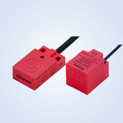
Proximity limit switches work based on the principle of detecting the presence of an object without physical contact. They use technologies such as magnetic fields, inductance, or capacitance.
For example, an inductive proximity limit switch can detect a metal object when it comes within a certain distance. In a conveyor system handling metal parts, this type of limit switch can sense the presence of the parts and control their movement.
IV. Installation and Adjustment
1. Mounting Location Selection
The limit switch should be installed at a location where it can accurately detect the position or movement of the object.
For example, in a machine with a moving carriage, the limit switch might be mounted at the end of the travel path of the carriage. The mounting should be secure to ensure that the switch does not move or vibrate during operation. In a factory environment, the switch might be mounted on a rigid metal bracket.
2. Actuator Position Adjustment
Some limit switches allow for the adjustment of the actuator position. This is useful when the exact position of the object to be detected needs to be fine-tuned.
For example, in a manufacturing setup, if the position of a workpiece changes slightly, the actuator of the limit switch can be adjusted to ensure proper detection.


